
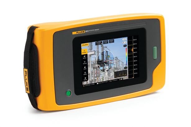
 TECHNICAL INSIGHTS · FLUKE · THERMAL POWER
Fluke for thermal power plants: early fault detection and precise instrumentation calibration
Plant reliability depends on electrical connections, insulation, rotating machinery, compressed air, vacuum systems and thousands of measurement points. Fluke and Fluke Calibration tools support a consistent workflow: screen for anomalies, verify the cause, calibrate instruments and confirm the result after maintenance. Tool selection should follow the failure mechanism and the asset’s operating conditions.
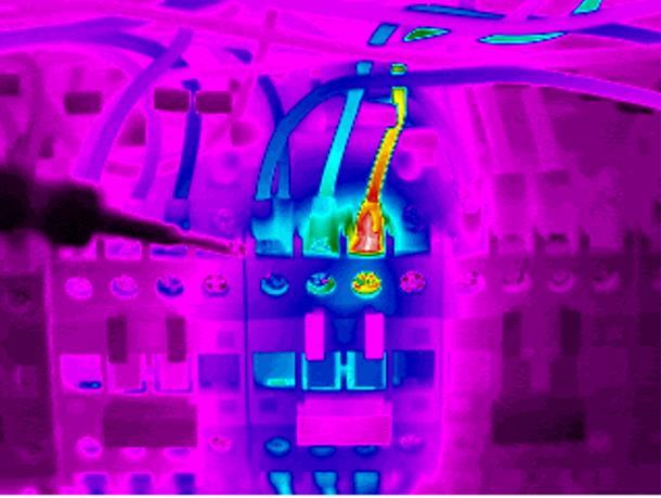
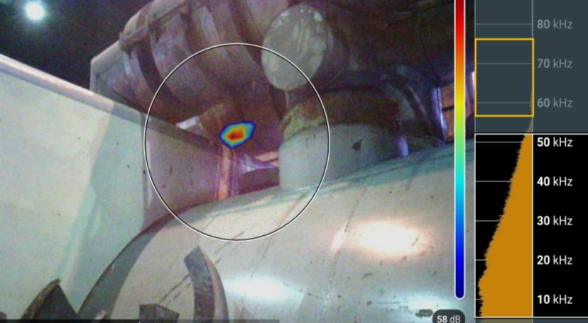
Product photographs: Fluke. Field survey images are extracted from the customer-supplied Nhiet Dien.pdf presentation and illustrate its applications; they are not SuperMRO project references.
Selection by maintenance task
| Task / asset | Reference selection |
|---|---|
| Connections, switchgear, transformers | Ti480 PRO |
| Compressed air / vacuum leaks | ii915 · LeakQ |
| Discharges / conveyor rollers | ii915 · PDQ / MecQ |
| Pumps, fans, motors | 805 FC / 810 |
| Grounding / soil resistivity | 1625-2 |
| 4–20 mA loops and transmitters | 773 / 789 / 754 |
| Automatic / bench pressure calibration | 729 / 729 PRO · P5514B + 2700G |
| Temperature sensors | 9142 / 9143 / 9144 + 1523 / 1524 |
1. Match the tool to the failure mechanism
A switchgear assembly may have both a hot connection and discharge activity; a fan may have bearing heat and abnormal vibration. Thermal images show surface temperature, acoustic images locate sound sources, vibration measurements describe machine behaviour and calibration establishes measurement error. Combine these findings with operating load, baseline data and asset history rather than using one image as a definitive diagnosis.
2. Thermal imaging for electrical and mechanical inspections
Inspect cable terminations, busbars, MCCs, auxiliary switchgear, transformer connections and cooling systems, motor surfaces and bearing housings. The Ti480 PRO has a 640 × 480 infrared detector and optional 2×/4× telephoto lenses. Select optics by target size and working distance, not display resolution alone. Record load, ambient conditions, emissivity, reflected temperature, distance and viewing angle; compare similar components under comparable conditions. Reflective metal and insulation can mislead interpretation. A thermal camera does not directly measure harmonics or confirm current imbalance. Follow up with electrical measurements when necessary. Suitable IR windows can support inspections under the plant’s safety procedure. Route-based handheld inspections do not replace a designed fixed 24/7 thermal monitoring system. [2]
3. ii915 acoustic imaging: three complementary inspection modes
The ii915 overlays SoundMap on a visible image and operates over a published 2–100 kHz range. LeakQ supports locating compressed-air, gas and vacuum leaks with conditional leak/cost estimates. PDQ supports discharge assessment and classification. MecQ screens mechanical acoustic anomalies, including conveyor rollers. Detection depends on emitted sound, distance, transmission paths, obstructions and background noise. Inspect air valves, fittings and regulators, tag confirmed leaks and rescan after repairs. Vacuum leaks require accessible acoustic paths and do not directly establish turbine efficiency losses. The supplied presentation describes hydrogen-cooling leak surveys at a South African plant: acoustic localization does not measure H₂ concentration or replace gas detectors. Confirm hazardous-area requirements and suitability before use. [1]
4. Discharge screening in switchgear and substations
Prioritize MV switchgear, insulators, connections and switchyard equipment. Acoustic classification is supporting evidence; it is not an apparent-charge measurement in pC under IEC 60270. Do not equate every arc with partial discharge. Metal enclosures and hidden sources can attenuate sound, so no acoustic indication is not proof of healthy insulation. Where confirmation is needed, select electrical, TEV, HFCT or UHF testing appropriate to the asset. Never open energized compartments merely to improve sound reception. [1]
5. 805 FC and 810 for rotating auxiliaries
Use 805 FC for repeatable overall-vibration and bearing-condition screening of pumps, fans and motors. Keep measurement position, direction, speed and load consistent. The 810 supports diagnosis of common imbalance, misalignment, looseness and bearing faults. Thermal and acoustic observations provide complementary evidence. Handheld tools do not replace dedicated turbine–generator protection, shaft-displacement monitoring or specialist rotor-dynamic analysis. [3][4]
6. Grounding tests: topology determines the method
The 1625-2 supports stake-based fall-of-potential, soil-resistivity, selective and two-clamp stakeless testing. Stakeless testing requires parallel ground-return paths; it is unsuitable for an isolated single electrode. A loop reading is not automatically the resistance of the complete switchyard grid. Assess topology, bonding, interference and test-electrode placement. Do not apply 5 Ω universally: acceptance follows design requirements, with step/touch voltages considered when assessing grid safety. [5]
7. 773, 789 and 754 for 4–20 mA loops
The 773 measures loop current without opening the circuit and can source/simulate signals. The 789 combines electrical measurements and loop functions; series-current work requires the plant’s operating procedure. The 754 measures, sources or simulates mA, mV, resistance, frequency, RTD and thermocouple signals, integrates HART and documents calibration results. Pressure measurement requires a compatible module; pressure generation requires an external source. It does not physically heat a sensor. For a linear 0–10 bar / 4–20 mA transmitter, I = 4 + 16 × P/10: 0, 2.5, 5, 7.5 and 10 bar correspond to 4, 8, 12, 16 and 20 mA. Injecting mA into a DCS tests only the mA-to-DCS segment. Span error is (measured − ideal current)/16 × 100%; acceptance comes from the instrument requirement and uncertainty budget. Square-root flow configurations require their actual transfer function. [6][7][12]
8. Automated pressure calibration and higher-pressure work
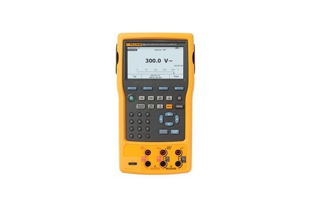
Evaluate 729/729 PRO for repeated transmitter and switch calibration. The 729 PRO incorporates automatic pumping/control, HART, leak tests and documented test points. Its 4M version controls up to 40 bar and 7M up to 70 bar. Published pressure accuracy is 0.02% FS under specified conditions; FS refers to the selected module’s full scale, making range selection important for low pressures. Use dry air or non-corrosive gases as specified; do not feed oil, water or hot steam into the pump. External modules can extend measurement without extending automatic generation. Higher-pressure steam/feedwater duties require suitable pressure sources, reference instruments, fittings, isolation and cooling. P5514B with 2700G provides a bench comparison system: the pump itself is not the measurement standard. Specify pressure type, fluid, range, threads, tolerance, HART and calibration certificates. [8][9]
9. Temperature calibration: test the electronics and the sensor separately
754 RTD/thermocouple simulation checks transmitters and indicators; testing the actual probe requires a physical reference-temperature source. The 9142, 9143 and 9144 ranges are −25 to 150 °C, 33 to 350 °C and 50 to 660 °C respectively. Choose inserts by probe diameter, immersion depth and uniformity, allow stabilization and use an appropriate reference. Display accuracy is not total calibration uncertainty; include reference-probe, stability, uniformity and conduction effects. Higher temperatures require another source. 1523/1524 are reference readouts with suitable probes; 1524 has two channels. Readout accuracy is not complete-system accuracy. Consider the certified 1552A Ex configuration where intrinsic safety is required, checking its exact approval conditions. Record as-found/as-left results, tag, range, test points, standards and acceptance criteria; verify software compatibility per model. [10][11][7]
10. A maintenance workflow that verifies the benefit
Organize three levels: routine screening, specialist diagnosis and expert root-cause analysis for critical assets. Pilot MV/MCC, compressed air, important fans/pumps and selected pressure/temperature loops. Establish baselines, rank anomalies by evidence and consequence, repair and repeat measurements under comparable conditions. Track confirmed/closed findings, route labour, passing calibrated loops and verified leakage reduction; one image cannot establish an energy-saving or downtime guarantee. SuperMRO can help match instruments, accessories and technical documentation to plant needs. Confirm model availability, certificates, software and support in the specific proposal.
Documentation and official sources
- Fluke ii915 Acoustic Imager
- Fluke Ti480 PRO Infrared Camera
- Fluke 805 FC Vibration Meter
- Fluke 810 Vibration Tester
- Fluke 1625-2 GEO Earth Ground Tester
- Fluke 773 Milliamp Process Clamp Meter
- Fluke 754 Documenting Process Calibrator-HART
- Fluke 729 PRO Automatic Pressure Calibrator
- Fluke Calibration P5514B Hydraulic Pressure Comparator
- 914X Series Field Metrology Wells — official brochure
- Fluke Thermometer Readout Selection Guide
- Fluke 789 ProcessMeter