
 TECHNICAL RESEARCH · COAL-FIRED POWER
REXA in coal-fired power plants: from precise actuation to a verifiable upgrade study
A good control algorithm cannot stabilize a plant if its valve or damper does not execute the command. REXA is relevant where force, speed, small movements and position holding jointly determine control quality. SuperMRO is a REXA partner with experience in the manufacturer’s products and can coordinate support from site assessment and technical planning through implementation and post-upgrade evaluation.
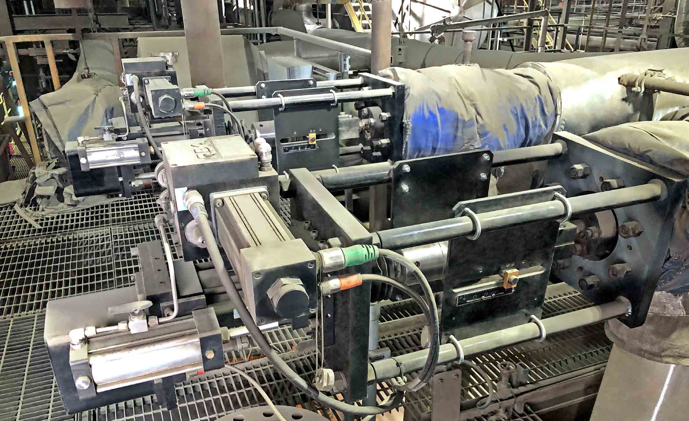
REXA example installation photograph, reproduced from Coal-Fired Power IB-8, page 7. This is not a SuperMRO project photograph and does not establish a particular plant’s configuration. [1]
SuperMRO analysis based on public REXA documentation, reviewed on 11 October 2026. Survey, testing and economic recommendations are proposed methods, not an approved design or measured Vietnamese plant results. Final configuration and ratings must follow manufacturer documentation for each equipment tag.
Quick terminology guide
| Term | Operational meaning |
|---|---|
| Electraulic™ | REXA’s electro-hydraulic technology, combining electronic control with a pump and self-contained hydraulic mechanism. |
| Final control element | The valve/damper and actuator assembly that actually changes process flow or pressure. |
| Deadband / deadtime | Position deviation that does not trigger correction / delay before response starts. Neither is full-stroke time. |
| Stiction / hysteresis | Breakaway friction producing stick–jump motion / direction-dependent response. |
| FD / ID / PA | Forced draft, induced draft and primary air; PA supports pulverized-coal drying and transport where applicable. |
| SH / RH / attemperator | Superheat / reheat / water-spray steam temperature conditioning. |
| Fail-in-place / fail-safe | Hold position / move to a defined safe state. Signal failure and power failure are distinct events. |
| Heat rate / FAT / SAT | Heat input per unit electricity / factory acceptance test / site acceptance test. Specify gross or net electrical output. |
01 · Diagnose the control loop before choosing equipment
Investigate drum level excursions after load changes, steam temperature hunting, stepped damper motion or valves moving only after commands accumulate. Align DCS demand, position feedback, process variable, unit load and interlocks on one time axis. A stationary position followed by a jump suggests an actuation limitation; good position tracking with an unstable process points toward valve characteristics, measurement, transport delay or control coordination.
Increasing PID gain will not remove linkage play or stiction. Integral action can accumulate while the valve sticks and then cause overshoot at breakaway. Establish root cause and loop criticality before choosing actuator replacement, valve repair or logic changes.
02 · How Electraulic works and why it matters
REXA electronics compare demanded and measured position. Beyond the configured deadband, a motor drives a reversible pump, moving oil between the chambers of a double-acting cylinder. At target position the pump stops and the Flow Match Valve arrangement holds oil to maintain position. This self-contained arrangement avoids instrument-air or central hydraulic-station dependence for this actuation function; the motor need not run simply to hold position. [2]
Hydraulic force and small-motion control are valuable together. Oil stiffness helps resist changing loads, but installed stiffness also depends on cylinder volume, brackets, shafts and linkages. Hydraulic locking is not an unlimited holding guarantee under every failure: leakage, configuration and fail-safe behavior still require verification.
03 · What 0.05% and approximately 70 ms actually describe
The XPAC Series 3 brochure lists an adjustable deadband of 0.05–5%, approximately 70 ms deadtime and a motor rated for 100% duty with no start/stop limit. These are selection indicators, not a guarantee of 0.05% flow accuracy, 0.05% overall process accuracy or a 70 ms full stroke. The brochure requires configuration-specific documentation for actual performance. [3]
A small deadband is useful only with clean signals and suitable mechanics; excessive sensitivity can follow noise. Separate resolution, repeatability, position error, reversal hysteresis and loaded speed. Procurement should specify small-step response and major travel under representative loads, in both directions, rather than unloaded full-stroke time alone. [4]
04 · FD/ID and furnace pressure: coordinated, forceful and sufficiently fast
In balanced-draft boilers, FD supply and ID exhaust cooperate to maintain the design furnace pressure, normally slightly negative. Fuel, incoming air and flue-gas flow do not change simultaneously during disturbances. A slow or force-limited drive can prolong pressure excursions. REXA damper drives merit assessment where substantial torque, rapid movement and continuous modulation are needed. [5][6]
First identify whether control uses dampers, inlet guide vanes, blade pitch or variable speed. Not every fan needs a damper-actuator upgrade. Review parallel-fan load sharing, fuel–air cross-limits, feedforward and OEM speed limits. A useful stroke time must satisfy furnace dynamics without mechanical impact. Furnace-pressure protection and trip logic remain independent layers.
05 · Primary air, hot/cold air mixing and burner tilt
Pulverizer hot/cold air dampers influence both mill outlet temperature and coal transport flow. Position error or linkage play can intensify interaction between those loops. Assess torque throughout travel, damper characteristics, tightness, airflow measurement, coal moisture and mill operating limits. Better actuation does not eliminate mill-fire hazards.
Burner tilt is a separate application in tangentially fired boilers equipped with tilting burners, adjusting heat distribution and supporting reheat temperature control. REXA damper drives can be considered, subject to corner synchronization, linkage condition and OEM travel limits. Do not assume applicability to CFB boilers or every coal-firing arrangement. [6]
06 · Drum feedwater control needs more than an actuator
Increasing steam demand can lower drum pressure and expand bubbles, temporarily raising indicated level while water inventory falls. Decreasing demand can cause the opposite shrink effect. Three-element control coordinates drum level, steam flow and feedwater flow; measurement quality and low-load mode transitions also matter. [7]
The actuator contributes stable small movements under changing differential pressure. Before retrofit, assess Cv, installed flow characteristic, packing, trim, startup/main-valve allocation and pressure-compensated level measurement. Once-through boilers do not manage a drum inventory in the same manner; drum-level criteria cannot simply be transferred to supercritical feedwater control.
07 · Feedwater recirculation: modulation and pump protection
Recirculation maintains pump minimum flow when boiler demand is low. High pressure drop makes this a severe service vulnerable to cavitation and trim erosion. Evaluate REXA holding force, protective opening and seating capability, but address cavitation through suitable valve/trim design. An actuator cannot restore damaged trim. Class V or similar shutoff is a valve-assembly requirement under defined test conditions, not an actuator-only certification. [8]
Minimum flow and NPSH are separate checks: meet OEM minimum continuous stable/thermal flow and the required available-versus-required NPSH margin. Fail-open is often considered for pump protection, but must follow plant cause-and-effect analysis. Closed-seat leakage wastes recirculated flow; excessively fast closure can create pressure transients.
08 · SH attemperation: small movement quality is central
At low load, the required superheat spray flow may be small while valve differential pressure and packing friction remain significant. Stick–jump movement can inject excess water before the delayed temperature loop responds. REXA is a candidate when testing identifies poor low-opening modulation as the limiting factor. [9]
Check nozzle atomization, evaporation distance, sensor location, seat leakage and minimum superheat required by design. Accurate valve position does not prove complete water evaporation. Trend spray flow with steam temperature, pressure and load, and establish safe operating boundaries before extending low-load capability. Combined-cycle examples on manufacturer application pages are not coal-unit savings evidence.
09 · RH attemperation: understand pressure drop and heat-rate limits
Steam leaving the HP turbine returns through the reheater and usually enters the IP turbine, with alternatives depending on design. RH steam pressure is lower than SH pressure; spray supplied from a high-pressure source may therefore produce a larger valve differential and higher cavitation risk. REXA’s dedicated RH page clarifies this relationship. Use actual upstream/downstream pressures instead of equating low steam pressure with low valve differential. [10]
Stable modulation may reduce unnecessary overspray caused by poor actuation. RH temperature strategy also involves burner tilt, air/fuel distribution, surface fouling and load. Less spray is not automatically better: turbine temperature limits remain decisive. Separate actuator effects from combustion optimization and maintenance performed in the same outage when assessing heat rate.
10 · Turbine bypass and supercritical startup are scenario-specific
Bypass systems coordinate pressure reduction and desuperheating during designed startup, load-changing and disturbance conditions. The actuator must meet loaded force and speed requirements, together with condenser capacity, vacuum, steam flow and spray-water limits. There is no universal HP/LP bypass opening time. Bypass does not replace turbine trip valves or overspeed protection. [11]
For supercritical once-through boilers, identify the OEM separator, recirculation/recovery circuits and startup valves. Preserve evaporator flow, pressure and safe mode transfer. Brochure startup diagrams illustrate particular arrangements. Retrofit engineering must cover complete sequences, directional speeds, fail positions and bypass permissives rather than replacing a drive while assuming all tuning remains valid. [12]
11 · Turbine governor control requires specialized approval
REXA’s coal-power documentation includes governor applications for generator turbines and, where used, feed-pump drive turbines. [1] This requires coordination with the turbine OEM, governor and protection system. Stiffness, dynamic response, linearity and required closure must be demonstrated at valve–actuator–controller assembly level.
A governing valve is not the same as a stop/trip valve. An EHC/HPU retrofit must define retained and replaced functions, trip interfaces, backup power, proof testing and applicable safety requirements. Attractive actuator specifications alone do not establish turbine-protection compliance. Treat this as a specialized engineering package with appropriate approvals and outage planning.
12 · Sootblowers, vents and condenser level: expose hidden losses
Sootblower steam-pressure control influences cleaning energy and steam consumption; balance cleaning against tube erosion and the cleaning sequence. For vent/drain valves, investigate closed leakage, startup modulation and safe discharge. Their safe failure positions cannot all be assumed open. Prioritize using operating history and actual losses rather than valve count. [18]
Jerky level-control valve motion around condensers or associated vessels can create flow and pressure oscillations. Distinguish actuator hunting from poor measurement, pipe arrangement and downstream-pressure changes. Concurrent position, level, flow and pressure data establish the necessary scope.
Application and priority matrix
| Location | Value to verify | Associated requirements |
|---|---|---|
| FD/ID dampers | Furnace pressure; load-change response | Furnace dynamics; cross-limits; fan coordination |
| PA / burner tilt | Mill temperature; transport; heat distribution | Boiler arrangement; synchronization; OEM limits |
| Drum feedwater | Level and flow stability | Three-element control; measurement; sizing |
| Pump recirculation | Minimum flow; leakage; protective response | Anti-cavitation trim; NPSH; cause-and-effect |
| SH/RH spray | Small spray-flow modulation; temperature stability | Nozzle; evaporation; pressure drop; leakage |
| Bypass / startup | Pressure tracking and startup sequence | Condenser limits; spray; turbine protection |
| Governor / auxiliaries | Control quality and reliability | OEM approval; trip; baseline evidence |
13 · Read field evidence in its original context
A November 2009 Power Engineering reprint describes Mirant ID-drive upgrades at Morgantown, Dickerson, Chalk Point and Potomac River. Selected full-stroke times differed by unit: approximately 6, 8 or 15 seconds. This historical evidence shows application-dependent speed selection, not a universal present-day damper guarantee. [15]
Keeping Control of Drum Levels describes PSEG Mercer feedwater upgrades involving both valves and actuators; outcomes cannot be attributed to the actuator alone. A manufacturer case from an unnamed South African supercritical coal plant reports more stable condenser level and resolved water hammer after retrofit. These support test hypotheses; they are not independent Vietnamese measurements or SuperMRO projects. [16][17]
14 · Compare technologies by the application
Consider REXA when a critical loop needs high force/torque, continuous modulation and good response without a central HPU. Proper pneumatic actuation with clean, adequately pressurized air and a suitable positioner can serve many duties well. Electromechanical drives can fit suitable modulation and speed requirements. Dedicated servo-hydraulic systems can also deliver high response and established safety functions.
Compare loaded test evidence, fail-safe needs, retrofit interfaces, power, maintenance skills and lifecycle cost. Do not presume all pneumatics perform poorly or all HPUs are unreliable. Replacing equipment that already meets its duty solely to standardize a brand creates little value; prioritize tags with demonstrated operating constraints.
Technology comparison
| Technology | Strengths and limitations |
|---|---|
| REXA Electraulic | Hydraulic force, continuous modulation, self-contained circuit; requires proper power, configuration and support. |
| Pneumatic + positioner | Effective in many duties; assess stiffness, air supply, friction and failure action. |
| Electromechanical | Useful across suitable duties; verify speed, modulation frequency, torque and fail-safe energy. |
| Servo-hydraulic / HPU | High response and dedicated architectures possible; evaluate oil, pipework, redundancy and actual maintenance. |
15 · Size force, torque and speed together
Linear-valve force includes differential pressure acting on effective area, packing friction, dynamic forces and required seating load in both directions. Rotary drives require torque-versus-angle data, bearings, pressure-loaded blades and linkage ratios. Brackets and foundations must be stiff; an oversized actuator cannot eliminate downstream backlash. [13][14]
Mechanical power is approximately force × velocity or torque × angular velocity. Higher speed at the same load increases power and hydraulic-flow demand, so the manufacturer must confirm power module, supply and travel. Force margin must not overdrive a damaged valve or exceed stem limits. Spring/accumulator sizing must satisfy required force at the end of fail-safe travel, not merely its initial movement.
16 · Signal failure, power failure and trip are different
IOM Rev.18 describes analog-input failure handling in Auto, including hold or motor-driven movement to a selected position when power remains available, and separate trip inputs for spring/accumulator configurations. A software fail-position setting does not supply mechanical energy after total power loss. [4]
Prepare cause-and-effect for power loss, broken 4–20 mA wiring, CPU fault, feedback loss and independent trip. Specify direction, speed, end force, accumulator recharge and reset conditions. Select open/close/hold per hazard analysis. Do not infer whole-system SIL from product descriptions; safety-function requirements need exact-model evidence, architecture and proof-test intervals.
17 · Site assessment and controlled change before the outage
Collect tags, P&IDs, valve/damper data, differential pressures and temperatures across load, travel, failure direction, torque/force, DCS interfaces, supply and mounting drawings with event trends. Include vibration, radiant heat, coal dust, washdown, any hazardous-area classification and accessibility. Actuator/enclosure ambient temperature is distinct from process-fluid temperature; remote electronics may be necessary under an approved configuration. [3][4]
Freeze bracket design, stem/shaft limits, cables, grounding, I/O, electrical protection, maintenance access and lifting plans. Back up parameters and manage changes to logic, alarms and interlocks. Capture baseline data before work, and record concurrent valve, nozzle or tuning changes so the result is not misattributed.
18 · FAT/SAT should prove behavior, not just travel
FAT should verify records, stroke, action, I/O, alarms, feedback, small steps, directional stroke times and fail-safe functions under representative test loads. SAT checks installed mechanics, true stem/damper travel, linkage and limits before approved process-loop tests. Agree acceptance criteria beforehand for each tag’s function and risk.
Do not initiate live trips or large process steps simply to obtain impressive plots. Power-loss, spray, bypass and governor testing need approved conditions, permits, isolation and OEM procedures. Reaching demanded position alone is insufficient: confirm improved process stability, no new oscillations, compatible interlocks and a complete operational handover.
Proposed acceptance plan
| Item | Assessment | Acceptance basis |
|---|---|---|
| Position and small steps | Demand, feedback and final-element position in both directions under load | Agreed error, repeatability and delay specification |
| Travel speed | Opening/closing with representative load and ramp limits | Required dynamics without mechanical overrun |
| Position holding | Observe drift with changing test loads | Design criteria; do not infer from unloaded tests |
| Failures and trip | Signal loss, power loss, trip and backup configuration | Approved cause-and-effect and test procedure |
| DCS and mode transfer | I/O, alarms, Auto/Manual and bumpless transfer | Compatible logic; correct alarms and feedback |
| Process-loop outcome | Trends at comparable load, fuel and conditions | Agreed KPIs and documented concurrent changes |
| Handover | As-built drawings, configuration, training and spares | Complete records and operational readiness |
19 · Quantify benefits without a generic saving promise
Potential benefits include reduced oscillation, settling delays, leakage or unnecessary recirculation, manual intervention and improved low-load operation within design limits. Heat-rate comparisons must use the same gross/net boundary and account for load, coal quality, ambient conditions and concurrent changes. A short test at one load cannot establish annual performance.
If ΔHR is in kJ/kWh, E in kWh and fuel LHV in MJ/kg, theoretical fuel reduction = ΔHR × E ÷ (1,000 × LHV), in kg, under valid comparison assumptions. Include equipment, engineering, outage, spares, training and maintenance in cash flow, with conservative fuel prices and event probabilities. Avoid double-counting extra electricity and fuel saving on the same basis. Use conservative, base and favorable cases rather than default marketing percentages.
20 · Reduced routine oil work does not mean no maintenance
REXA describes a closed hydraulic circuit requiring no routine fluid maintenance by product design. [3] Installed assemblies still need leakage, fastener, linkage, bracket, enclosure, cable, feedback and alarm inspections. Spring/accumulator options require configuration-specific checks and proof tests. Opening circuits or managing stored pressure must follow manufacturer instructions and energy isolation.
Select spares by criticality and lead time; retain serial/model records, configuration backups and task-specific training. Trend demand–position deviation, movement time, manual overrides and alarms after retrofit. These indicators can reveal changing friction or linkage condition before process control deteriorates.
21 · SuperMRO and REXA: evidence-led implementation
As a REXA partner experienced in its products, SuperMRO can help screen critical loops, coordinate manufacturer configuration confirmation, develop mechanical/electrical/control proposals and support implementation and post-upgrade assessment. A practical sequence is survey and baseline → prioritized tags → design confirmation with relevant OEMs → FAT → installation and SAT → KPI monitoring across operating loads.
The goal is to solve the unit’s real constraints and make results verifiable. Industrial Trust grows through justified equipment choices, controlled change, informed operators and performance demonstrated by data.
References
- REXA — Coal-Fired Power, IB-8 (example installations: p. 7)
- REXA — Electraulic Actuation
- REXA — XPAC Series 3 brochure, Product Design, Performance and Compliance, p. 15
- REXA — XPAC Series 3 IOM, Rev. 18; control parameters pp. 57–60
- REXA — Furnace Draft Pressure Control
- REXA — XPAC Series 3 Damper Drives
- REXA — Feedwater Regulator for Drum Boilers
- REXA — Boiler Feedwater Recirculation Valve
- REXA — Superheat Attemperator
- REXA — Reheat Attemperator
- REXA — Turbine Bypass System Control
- REXA — Supercritical Plant Startup Control
- REXA — XPAC Series 3 Linear Actuators
- REXA — XPAC Series 3 Rotary Actuators
- Drew Robb — Mirant Deals with Upsets and Transients in Coal-fired Boilers; Power Engineering, November 2009; reprint hosted by REXA
- Joe Zwers — Keeping Control of Drum Levels; reprint hosted by REXA
- REXA — Supercritical Power Plant Condenser Level Control; manufacturer case study
- REXA — Coal-Fired Boilers / application library