
 TECHNICAL INSIGHT · OFFLINE OIL FILTRATION
STAUFF SMFS-U mobile oil filtration: cleanliness control from filling to operation
In industrial hydraulic and lubrication systems, oil condition affects pumps, valves and moving surfaces. Fresh oil may not meet the cleanliness required by the equipment, while service oil can acquire contamination through the environment, maintenance and wear. STAUFF SMFS-U filter carts provide an independent filtration circuit for transfer and offline circulation. This article examines the three brochure models, the meaning of their specifications and the considerations for plant deployment.
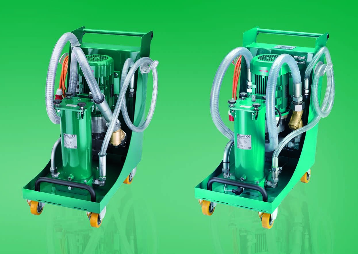
Image: SMFS-U-110 (left) and SMFS-U-CM-110 (right), STAUFF. Specifications and trials: Info Brochure Mobile Filtration Systems, reference 9910000352, 11/2015. Application analysis: SuperMRO. Confirm the current configuration against the exact order code and operating instructions.
1. An independent offline filtration circuit
A dedicated gear pump and motor draw oil, pass it through the filter and return it to a reservoir or transfer it into another container. In circulation mode, this kidney-loop treats a portion of the reservoir continuously, independently of the main hydraulic circuit flow. The brochure covers filtering fresh oil during transfer and cleaning existing hydraulic and lubrication systems, with mobile or stationary offline use. Connecting to an operating system still requires assessment of take-off and return points, pressure and safety. A cart does not replace the system pressure filter and must not be assumed suitable for a high-pressure connection. [1]
2. Three models and their configurations
All three models use a housing for NR-630 elements. SMFS-U-060 provides nominal flow of 60 L/min; SMFS-U-110 increases this to 110 L/min. SMFS-U-CM-110 has the same 110 L/min nominal flow and adds cleanliness, moisture and temperature monitoring with target-based stopping. Actual flow depends on viscosity and operating conditions. The figures below describe the November 2015 brochure versions, rather than every subsequent ordering variant. [1]
| Model | Nominal flow | Motor | Clogging indicator | Monitoring |
|---|---|---|---|---|
| SMFS-U-060 | 60 L/min | 2.2 kW | Visual HI-A | — |
| SMFS-U-110 | 110 L/min | 4 kW | Visual HI-A | — |
| SMFS-U-CM-110 | 110 L/min | 4 kW | Electrical HI-E | Particles · RH% · temperature |
3. NR-630 and 4Pro: fine filtration versus pump protection
The brochure lists inorganic glass fibre elements rated 3, 6, 10, 16 and 25 µm. Its 4Pro media are intended for high dirt holding capacity and filtration performance. A screw-cap housing allows element replacement without special tools. A separate washable stainless-steel 200 µm inlet mesh protects the pump from coarse contamination; it is not the NR-630 fine filtration stage. Choose the fine element according to the equipment OEM cleanliness target, contamination load and permissible differential pressure. A micron rating alone does not define full filtration efficiency: comparisons require the beta ratio, test conditions and actual element configuration. One pass cannot be assumed to deliver a universal ISO code. [1]
4. Viscosity and electrical supply
Permitted viscosity is 12–800 cSt; the recommended range for continuous operation is 20–100 cSt. These ranges have different meanings: the ability to handle high-viscosity oil does not make operation at the upper limit the preferred continuous duty. Cold or viscous oil increases suction resistance and element differential pressure. Check oil temperature, hoses and pump supply conditions before starting. Brochure units use 400 V AC, three-phase, 50 Hz power with a CEE 16 A, 3P+N+PE plug and IP55 motors. They are not directly compatible with an ordinary 220 V domestic outlet. Qualified personnel should check electrical supply, grounding and rotation. [1]
5. CM-110: measuring cleanliness during filtration
The CM version integrates an eight-channel particle counter and a moisture/temperature sensor. The display shows ISO 4406 codes at >4, >6 and >14 µm, oil temperature, relative humidity RH%, total operating hours and resettable job hours. Operators can enter a cleanliness target; the brochure describes automatic motor stopping one minute after reaching it. The measuring unit is hydraulically and electrically separated in its own cabinet. Included LasPaC II View software connects through USB for configuration and analysis. RH% is not water content in ppm or water mass fraction; interpretation depends on temperature and fluid characteristics. Moisture measurement must not be mistaken for vacuum dehydration capability. [1]
6. Interpreting the brochure trials
One transfer example uses SMFS-U-CM-110 with a 3 µm element to move 800 L of HLP-HM 68 in seven minutes. Oil temperature is 14°C and viscosity at that temperature is 300 cSt, whereas the grade reference of 68 cSt is stated at 40°C. These specific conditions are not a time guarantee for other fluids. A separate offline filtration example changes ISO 4406 cleanliness from 22/21/17 to 14/13/8. The table below reproduces particle counts per 100 mL, not per mL. The reduction describes the complete circulation trial, not a single-pass element efficiency or a guaranteed outcome for every reservoir. [1]
| Size threshold | Before (particles/100 mL) | After (particles/100 mL) |
|---|---|---|
| ≥4 µm(c) | 3 285 656 | 10 360 |
| ≥6 µm(c) | 1 327 063 | 3 361 |
| ≥14 µm(c) | 82 894 | 336 |
7. Flow selection: one turnover is not a cleanliness guarantee
A preliminary theoretical turnover time is t = V/Q, using reservoir volume V and actual flow Q. For a 2,000 L reservoir, assuming nominal flow, a turnover takes approximately 33.3 minutes at 60 L/min or 18.2 minutes at 110 L/min. These are SuperMRO calculations, not manufacturer test results. Reservoir oil continuously mixes, so one turnover does not mean every portion has passed through the element once. Time to target also depends on initial contamination, continuing ingress, suction/return arrangement, element efficiency, actual flow and mixing. For large reservoirs, acceptance should use achieved cleanliness and its stability rather than runtime alone.
8. Features for maintenance work
Three-metre wire-reinforced suction and return hoses, lance holders and a handle support movement between maintenance points. The frame has four heavy-duty rollers, with steerable rear rollers. The 060 and 110 use an automatic-reset visual HI-A clogging indicator; CM uses electrical HI-E indication and an on-screen element-change message. The housing includes a drain plug. Motor overload protection and undervoltage protection prevent unintended restart following power or phase failure. The brochure describes a pump pressure-control valve set to 10 bar and shutdown monitoring against dangerous pressure caused by kinked hoses, high viscosity or a clogged element. This protection setting is not a universal customer-circuit connection rating: verify permitted operating pressure in the instructions for the exact model. [1]
9. Suitable applications and treatment boundaries
For compatible mineral oils, applications to assess include press hydraulic power units, hydraulic systems in steel, cement and mining plants, and suitable lubrication reservoirs. A shared cart can serve multiple reservoirs, filter fresh fill oil and support post-maintenance cleaning. These are application suggestions requiring site assessment. The brochure specifies mineral oil compatibility; it does not establish compatibility with phosphate-ester EHC fluid, water-glycol or all synthetic oils. It also does not confirm vacuum dehydration, acid removal or dissolved-varnish treatment. When water, oxidation or chemical degradation dominates, oil analysis should guide additional treatment technology. Particle elements are not a complete remedy for every contamination mechanism. [1]
10. Deployment and acceptance at the plant
Before operation, identify the fluid and OEM cleanliness target, take a representative baseline sample, and inspect power supply, rotation, suction sealing and hose/lance cleanliness. Position suction and return to avoid air entrainment, unnecessary bottom-sediment disturbance and short circulation paths; follow the operating instructions for starting and oil supply conditions. Monitor clogging indication, temperature and cleanliness during operation. Do not keep running to compensate for a blocked element. After treatment, sample using the same procedure and record fluid, temperature, runtime, element and before/after ISO codes. CM readings support monitoring; independent sample analysis may still be required by the plant acceptance procedure. When sharing a cart, control retained oil and cross-contamination between incompatible fluids.
11. Selection checklist and investment assessment
Collect fluid identity, viscosity at working temperature, reservoir volume, existing and target ISO codes, available treatment time, mobility, electrical supply, take-off/return arrangement, reporting needs and spare element availability. Consider CM when direct monitoring, target-based stopping and data management are required; a non-CM version may suit plants with independent instruments and sampling procedures. Economic assessment should use measured element consumption, operating hours, electricity, oil replacement, contamination-related failures and downtime. There is no justified universal savings percentage or oil-life extension for all applications. Confirm the ordering code and current instructions because configurations can change after the 2015 brochure. [2][3]
12. Filtration within condition-based maintenance
SMFS-U is most useful within a contamination-control programme: filter oil before filling, prevent dust and water ingress, keep maintenance tools clean, trend oil samples and correct contamination sources. The range spans basic mobile filtration and monitored filtration. Selection should connect fluid compatibility, cleanliness targets and plant procedures. The original brochure is linked below so readers can check trial conditions and specifications before progressing from preliminary selection to technical confirmation.